 Planar Surface
Introduction
This topic will explain the Planar Surface function, will explain where to find the function, and explain the options found in it. This topic will also explain creation with quick steps and an example, and provide links to related topics.
The Planar Surface Function
The Planar Surface function creates a planar surface from a closed 2D geometry chain. This can be one or more closed chains and the chains can also be nested.

Navigation
To open Planar Surface:
-
In the Surfaces group, of the Create 3D ribbon, click
 Planar.
The parameters display in the Data Entry Manager.
The Data Entry Parameters
-
 Preview - Select the check box to enable the CAD preview, which displays what the result will be before you create it. Once all geometry is selected, the preview is shown.
  Preview - Clear the check box
to turn off the CAD preview.
Preview - Clear the check box
to turn off the CAD preview.
Selected Geometries
The Selected Geometries list, shows all entities chosen for the creation of a Planar Surface.
|
|
|
| The list box will list the entities currently selected for the function. | |
 (Delete All)
- removes all entities from the list.
(Delete All)
- removes all entities from the list.
- OK - finalizes the function.
- Cancel - exits the function.
Quick Steps - Planar Surface
- Open the function.
The Selected Preview list automatically has focus. - Select the 2D chains from which you want
to create the planar surface.
This can be one or more chains, and you can use single selection, window selection, or chain selection.
The geometry is added the Selected Geometry list.
A preview appears showing the current result. - Click OK to confirm.
The feature is added to the CAD Tree. - Repeat as necessary.
- Click Cancel to exit the function.
Example
Note: In the images below, both the Show Axis X-Y and Show Gnomon toggles have been disabled in the Axis X-Y group of the Settings Part > Display dialog.
- In the Quick Access Toolbar, click
 New.
New. - Click anywhere in the graphics area, to give it focus,
and press Ctrl+7 to select
the ISO 2 view.
- In the Shapes group, of the Create 2D ribbon,
click
 Rectangle.
The Rectangle parameters display in the Data Entry Manager and the Preview appears showing the default values.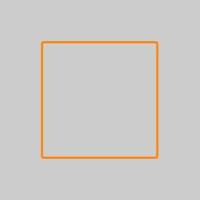
- In the Corner Type group, click
 to create chamfered corners.
The preview updates.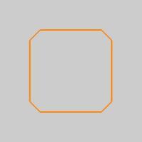
- Input 0.3750
for the Chamfer Length.
The Preview updates.
- In the Base Point group, leave the default value of 0.000 for the X,
Y, and Z
positions and click OK to
confirm.
A rectangle is created in the graphics area.
- In the Entity group, of the Create 2D ribbon, click the down arrow under
 Arc, and select
  Arc Center.
The Arc Coordinate parameters display in the Data Entry Manager and the Preview appears showing the default values.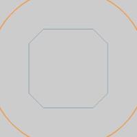
- Change the Radius
value to 0.3750.
The Preview updates.
- Click OK to
confirm.
An arc is created inside of the rectangle.
- In the Surfaces group, of the Create 3D ribbon,
click Planar.
- While holding the Shift key, click on one of the entities
the rectangle is comprised of in order to select the entire chain.
The individual entities the rectangle is comprised of are added to the Selected Geometries list, and the Preview updates.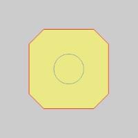
- Click on the arc to add it to the Selected Geometries
list.
The Preview updates.
- Click OK to
confirm.

The Planar is created in the graphics area and aPlane Surface feature is added
to the  CAD
Tree.
CAD
Tree. - To end this function, click Cancel.
That concludes this example.